
Aptitude Trainer and Software Developer
This circuit extends the two transistor astable multi-vibrator to add a third transistor so that a moving dot effect is obtained. The duty cycle is 1:2 - one high followed by two low. See the waveform shown below. As you can see tOFF = 2 x tON, which comes to a duty cycle of 33⅓ %. In the circuit below, I have added three transistors for inverting the outputs so that LED can be driven to give the effect of a running dot.
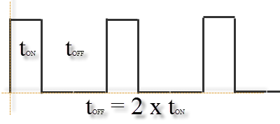 waveform generated by this circuit
 The Circuit Diagram
This is the circuit diagram for this project.
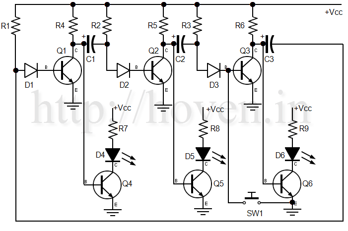 three transistor and three LED astable multivibrator
 Parts List
Following is the parts list for this circuit. There are 25 parts excluding the power supply.
- Transistors Q1-Q6 are all BC547 or BC147 or if these are not available you can use any switching transistor available in your local market.
- Diodes D1-D3 are all IN914 or IN4001 or any switching diode available in your local market.
- LEDs D4-D5 are red.
- Resistors R1, R2 and R3 are 100kΩ[hundred kilo-ohms], ¼W. Use any available tolerance.
- Resistors R4, R5 and R6 are 10kΩ[ten kilo-ohms], ¼W. Use any available tolerance.
- Resistors R7, R8 and R9 are 470Ω[four seventy ohms], ¼W. Use any available tolerance.
- Capacitors C1-C3 are 10μF/25v[ten microfarads/25volts] electrolyte. Use any available tolerance.
- Switch SW1 is a push-to-on switch. It is used to destabilize and boot the circuit so that it can start running. It is required to be pushed and released just once.
- Vcc is 6v. It need not be regulated. If you do not have 6v, you can safely use 5v. You can go as high as 12v, but you should increase R7, R8 and R9 to higher values[say, 1kΩ] so that the current through the LEDs remains within permissible limits.
Calculations
In the above circuit, if R1 = R2 = R3 = R, and C1 = C2 = C3 = C, then the value of tON = 0.81 x C x R seconds[VCC = 6v], if the units of R are in ohms and those of C are in farads[some countries call them faradays]. The value of tOFF is 2 x tON = 1.62 x C x R seconds. These times are dependent on VCC. The derivation of this formula is explained in the video below.
With the values given in the above circuit R = 100k and C = 10μ, so tON = 0.81 x 100000 x 10 x 0.000001 = 0.81 seconds. If you want different value, then you can use different values of C and R. You can even modify the above circuit to include a variable resistance. Only one variable resistance is required. Watch the video below to know where to place that resistance, and how to calculate its value.
Assembling this Circuit
I do not recommend assembling this on a breadboard unless you are testing the basic functionality. If you want to test the basic working of this circuit, then you can remove the lower three transistors[Q4-Q6] that drive the LEDs and test the simpler circuit of three transistors Q1-Q3. Don't forget that SW1. Without pressing it, the circuit may not work because all three transistors start in an equilibrium state. Then you can either use an oscilloscope or a multimeter to check the voltage variations at the collector of, say, Q3. Once you are satisfied about the working then you should solder the entire circuit on a general purpose PCB. Solder with patience, and test each connection with a multimeter. Be very careful about the polarities of the diodes and capacitors. The collector, emitter and the base of the transistors should be soldered in the correct way because when you see a PCB from the lower side, the three terminals appear to us cyclically rotated.
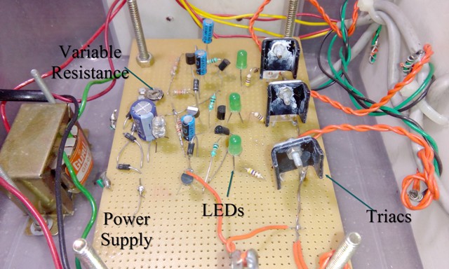 the photo of the circuit assembled by the author
 Video of the Assembled Project
This is a video of the assembled and running project that we have uploaded on youtube. This video shows all the three LEDs blinking live.
The Operation Explained
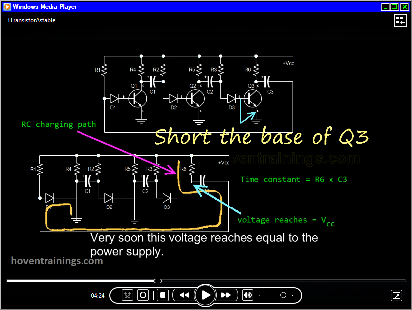
The operation of this circuit as well as the derivation of the formula for the duty cycle has been explained in the video that is contained in the file below. The formula that helps us calculate the ton = R x C x ln [((2 x Vcc) - 1.7)/(Vcc - 1.4)]. It's complete derivation has been given in the video contained in the installation below.
Screenshots
This is a screenshot of the software that should give you a good idea of the video that is contained there. Click on the image to see a larger view.
Installation
This software doesn't require any installation. Just download and double-click to run it. It doesn't require administrative priviliges to run. It runs in limited access mode, so should be very safe.
Supported Operating Systems
This video can be run on 32-bit as well as 64-bit versions of the Microsoft Windows Operating Systems. Windows XP and all later OS are supported. If you want to run it on Windows XP and Windows Vista, then you must also have the .NET Framework Version 3.5 installed on your machines. Those users who have Windows 7 and later donot have to worry because these operating systems already have the .NET Framework installed on them.
Download Links
DISCLAIMER: Even though every care has been taken in making this software bug-free, but still please take a proper backup of your PC data before you use it. We shall not be responsible for any damages or consequential damages arising out of the use of this software. Please use it solely at your own risk.
Please download the software here.